 English
 Español



Building 1, Block 4, Wufeng Industrial Park, Daxi Town, Taizhou City, Zhejiang Province, China
A motor design usually starts with the machine that needs to be driven. Power, speed, load behavior, available space, and operating conditions all influence the final structure. Treating a motor as an isolated component can create problems during installation, since electrical performance may fit the application while the physical arrangement does not.
Load behavior deserves attention early in the process. Some machines operate with a relatively steady load, while others face repeated starts, stops, direction changes, or sudden resistance. Such differences affect how the motor needs to respond during operation.
Power supply is another basic consideration. Voltage, frequency, phase arrangement, control method, and available electrical connections need to match the intended working environment. A design based on incomplete power information may require changes later in production.
Mechanical requirements should be recorded alongside electrical requirements. Useful information includes:
- Available installation space
- Mounting position
- Shaft direction and length
- Connection arrangement
- Expected operating duration
- Load characteristics
- Cooling conditions
- Surrounding temperature and moisture
A clear requirement sheet gives designers a practical starting point. Once the application is defined, electrical and mechanical decisions can be developed together rather than handled as separate tasks.
How Is the Motor Structure Matched With the Equipment
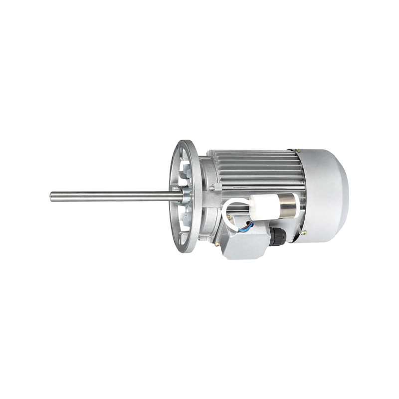
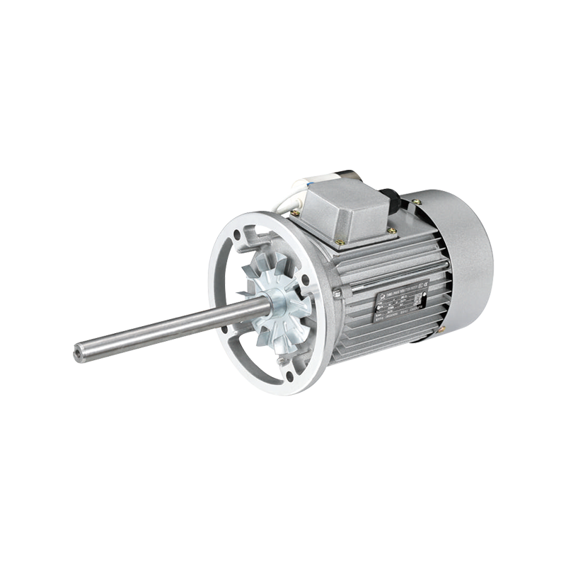
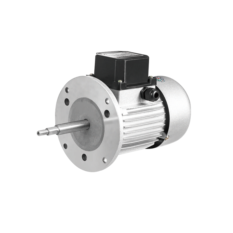
Physical compatibility often determines whether a motor can be installed without changing the surrounding machine. Housing size, mounting holes, shaft dimensions, shaft position, and overall length may need adjustment to fit a particular piece of equipment.
Limited installation space creates another design challenge. A motor may need to fit into a narrow compartment where airflow is restricted. Reducing external dimensions alone is not enough, since internal components still require sufficient space and operating conditions must remain suitable.
Shaft design also depends on the driven equipment. Shaft length, diameter, extension position, and connection method can change according to how power is transferred. A mismatch at the shaft can prevent proper assembly even when electrical characteristics are suitable.
Mounting method has a similar effect. Some machines require a horizontal arrangement, while others place the motor vertically or within a confined frame. Housing geometry and bearing support need to accommodate the selected position.
| Application Requirement | Possible Design Concern |
|---|---|
| Limited installation space | Housing size and cooling |
| Unusual shaft position | Shaft extension and mounting |
| Variable load | Torque response and winding design |
| Long operating periods | Heat management |
| Moist environment | Housing and sealing |
| Frequent starts | Starting behavior and component stress |
An existing motor structure can sometimes be modified to meet a new application. Such an approach may involve changes to the shaft, housing, winding, mounting arrangement, or cooling path rather than creating every part from the beginning.
How Are Electrical Characteristics Adapted
Electrical design connects the motor with the available power source and the mechanical load. Voltage, speed, torque, winding arrangement, and operating pattern need to work together rather than being selected independently.
Speed requirements are closely related to the driven machine. A pump, fan, conveyor, or other mechanical system may respond differently to changes in motor speed. A suitable design therefore begins with the required movement of the equipment rather than selecting a motor speed in isolation.
Torque requirements become important during starting and changing loads. A machine with greater resistance during startup may need a different electrical arrangement from equipment that begins under a light load. Repeated starting can create another set of demands because electrical and mechanical components experience repeated changes in operating conditions.
Power supply characteristics also affect the internal arrangement. A design intended for one type of electrical supply may not be suitable for another without changes to the winding and related components.
Control requirements should be considered at the same stage. A motor operated directly from a fixed supply has different needs from one connected to a control system that changes speed or operating behavior.
Rather than focusing on a single electrical value, designers generally need to consider how several conditions interact. A change in speed can influence torque, heat, current, and mechanical response, so adjustments in one area may require review elsewhere.
How Does Thermal Design Affect a Custom Motor
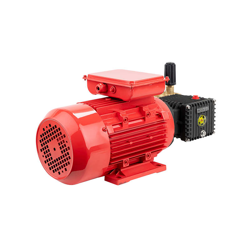
Heat is a natural part of motor operation. Electrical resistance, mechanical movement, and load conditions all contribute to temperature inside the housing. For a customized design, heat management becomes particularly important when the motor must fit into a compact space.
A larger housing can provide more room for internal components and may allow easier heat movement. A compact housing has less physical space, so internal arrangement and cooling need greater attention.
Operating duration also changes thermal requirements. A motor used for short periods may have a different heat pattern from one that runs continuously. Repeated starting can create another thermal condition because the motor experiences periods of increased electrical demand.
Cooling depends partly on the surrounding equipment. A motor placed inside an enclosed machine may have less airflow than one installed in an open area. Dust, moisture, or nearby heat sources can further affect the way heat leaves the housing.
Design decisions may therefore include:
- Internal component arrangement
- Housing shape
- Air movement around the motor
- Heat transfer through surrounding parts
- Protection from environmental conditions
Thermal checks should begin during design rather than being treated as a production‑stage correction. A motor that fits mechanically may still require structural changes when heat cannot be managed under actual operating conditions.
How Are Materials Selected for Different Operating Environments
Material selection depends on where a motor will work rather than on electrical requirements alone. Moisture, dust, vibration, heat, and contact with surrounding equipment can gradually affect different parts of a motor. A design intended for an indoor machine may therefore need different material choices from one installed in a damp or exposed area.
Housing material needs to provide suitable mechanical support while allowing heat to move away from internal parts. Surface treatment can be considered where moisture or other environmental exposure may affect the housing. Internal insulation materials require similar attention because electrical parts need stable separation during normal operation.
Shaft material is influenced by load and connection conditions. Repeated rotation places continuous stress around the shaft and its connection with the driven machine. Bearing selection needs to match the shaft arrangement and expected movement, while seals can help limit the entry of moisture or dust around rotating sections.
| Working Environment | Main Material Concern |
|---|---|
| Dry indoor space | General structural and electrical insulation needs |
| Damp area | Moisture resistance and sealing |
| Dusty area | Protection around openings and moving parts |
| High heat area | Insulation and heat management |
| Vibration prone equipment | Mechanical strength and secure assembly |
Material selection also needs to consider contact between components. Two materials may work separately while creating unwanted wear when placed together. Surface condition, lubrication, fastening, and movement all influence how parts behave during long operation.
For a Custom Electric Motor, environmental information should therefore be collected before component selection is finalized. A small change in installation conditions can affect housing design, sealing, insulation, shaft treatment, or cooling arrangements.
How Does Prototype Testing Refine the Design
A drawing can show dimensions and component positions, yet actual operation reveals issues that may not appear during design work. Prototype testing provides a practical way to check whether electrical behavior, mechanical fit, and heat management work together.
Testing normally begins with basic operation. Rotation direction, starting behavior, unusual noise, vibration, and connection stability can be checked before more demanding operating conditions are introduced.
Load testing provides another useful stage. A motor may behave normally without a connected machine and respond differently once resistance is applied. Changes in temperature, sound, vibration, and operating response can reveal areas that need adjustment.
Mechanical fit should be checked as well. A shaft can have the correct basic dimensions while still creating problems during installation because of limited clearance or an unsuitable connection position.
Practical checks can include:
- Installation fit
- Starting and stopping behavior
- Rotation stability
- Temperature changes
- Noise and vibration
- Shaft connection
- Housing condition
Testing becomes particularly useful when a motor will operate in a machine with unusual space or load requirements. Real working conditions provide information that cannot always be obtained from individual component checks.
How Does an Electric Motor Factory Turn a Custom Design Into Production
Once a design has been checked, production requires a clear connection between drawings, components, assembly steps, and inspection. Custom work can involve different dimensions or component combinations, so production staff need accurate information before assembly begins.
Component preparation comes before final assembly. Housing parts, shafts, bearings, electrical components, and other parts need to match the approved design. Mixing components from different specifications can create problems even when individual parts appear similar.
Winding and assembly require controlled processes because small changes can affect electrical behavior or mechanical balance. Connections need to follow the design, while rotating components need proper positioning inside the housing.
Inspection takes place throughout production rather than only after assembly. Checking dimensions before assembly can prevent later fitting problems. Electrical checks can identify connection errors, while mechanical inspection can reveal shaft alignment or housing issues.
A practical production flow can be viewed as:
Requirement review → Design preparation → Component production → Assembly → Inspection → Functional testing
Clear identification becomes especially important for custom orders. When several motor configurations are being produced, drawings, components, and inspection records need to remain matched with the correct design.
An Electric Motor Factory therefore has to manage both engineering requirements and production consistency. Customization does not end when a drawing is approved; manufacturing needs to reproduce the intended structure in a controlled manner.
What Should Be Reviewed Before Finalizing a Custom Motor
Final review should cover the complete working situation rather than one isolated motor characteristic. Electrical compatibility, physical installation, load behavior, cooling, materials, and maintenance requirements can influence one another.
A useful review can focus on several areas:
- Electrical: power supply, speed, torque, starting behavior, and control requirements
- Mechanical: housing dimensions, shaft arrangement, mounting position, and available clearance
- Environment: moisture, dust, heat, vibration, and surrounding equipment
- Thermal: operating duration, airflow, heat sources, and internal arrangement
- Maintenance: access to components, inspection needs, and replacement considerations
Installation details deserve a final check because a motor can meet the intended electrical requirements while creating difficulties once placed inside the actual machine. Shaft clearance, cable position, mounting access, and surrounding airflow should be reviewed before production is fixed.
Maintenance can influence design choices as well. A motor installed in a confined machine may be difficult to remove, so access and component arrangement can affect future service work. A design that considers maintenance from the beginning can reduce unnecessary changes during equipment installation.
Custom motor design is therefore a process of matching electrical behavior, mechanical structure, environmental conditions, thermal needs, and production requirements. A clear understanding of the driven equipment gives each design decision a practical purpose, while testing helps confirm whether the selected arrangement works under real operating conditions.


